• Welcome to H4O! For a reduced ad experience, please login or register with the forum.

H2 Onboard Air install with a York Compressor. Start to finish

Chastan

Well-Known Member
Messages
149
Location
Reedsburg, WI
POST #1 CHAPTER ONE
History and Project Goals

(posts have been updated with some new photos 10/27/11)
This is going to be a large set of posts (8) so start reading but be prepared for a long one. Due to the length and the number of pictures I am going to break this up into sections. Bear with me as I try to present it in a clear and manageable way.

Some teaser photos…
acp64.jpg

acp69.jpg

acp38.jpg

acp54.jpg


A little history
As many of you know, in the Jeep world they have been converting York Air Conditioner compressors in to onboard air compressors for years. The unique aspect of the York design is that unlike most air conditioner compressors that use the refrigerant (Freon in the old days) as the lubricant the York design uses a separate oil reservoir to keep the moving parts oiled. So if you remove the refrigerant from the system you have an instant air compressor. Add to this that the York model was used on dozens of car and truck models for decades so they are readily available.

You can find several great write ups on installs into Jeeps and even a couple other vehicles. In all my searching I have not found anyone that has done an install into a HUMMER.

The main reasons I drifted to this type of set up for an onboard air system include:

The volume.
Much more air through this system then any electric set ups out there. I will not only be able to air back up all four tires in record time, I also can run air tools like I was in my garage at unlimited duty cycle and instant high PSI.

Tied to the engine not to the electrical system load.
For me I would rather rely on a V-belt that I can change out then another high amp load on the electrical system. Of course if my engine is dead I will only have what air is in my tank but if your engine is dead how long can you run and electric compressor before the battery goes dead.

Established track record.
I may be the first (as far as I can tell) to put one on a hummer but there are hundreds maybe thousands out there in jeeps and other vehicles and the documentation of installs and nuances to go with that history.

Goals
So I had some goals before I started. Me, being the cheap bastard I am, wanted to spend a fraction of what a “kit” costs. You can buy everything you need (except hummer bracket as it does not exist) for $1,200 - $1,400 as a package. As you will see at the end I did this on the cheap by finding deals on the expensive elements and building what I needed myself.

I also knew this was going to be a fun one to put together. This project involved lots of designing, welding, plasma cutting, milling machine, electrical wiring, air system plumbing, vehicle parts, painting, fabricating, etc.

Finally, I wanted something that had a real pragmatic application not just looked pretty. Airing up after trail rides has always been a thorn in my side both in finding a location and the time it takes to get those 37’s back up to 50 psi. What do they say…. “The right tool for the job” well I wanted the right tool so here is what I did…
 
Last edited:

Chastan

Well-Known Member
Messages
149
Location
Reedsburg, WI
Post #2 Onboard air

Post #2 CHAPTER TWO
Planning the install

I was patient and searched for a few months for the primary parts that could not be picked up locally. I needed the compressor, air tank (specific size), alternator pulley and a good coalescent filter to separate the air and moisture coming out of the compressor. I also took the time to draft out some plumbing designs and electrical wiring diagrams (including relays, etc) so I knew what I was going to need before I started.

Gathering the materials
At the end I have a complete list of parts and materials. Some of the unique items I found or had to get creative with included:

Dual alternator pulley
This will have both a 6 groove serpentine belt groove and a V belt groove on it. I searched and searched but in the end this was the one item I could only find from the main supplier of these kits (Kilby air
http://www.onboardair.com/compressors.htm) for $65. One alternative is to find a compressor with a 6 groove clutch wheel and tie it into the main serpentine belt. I chose not to do this so I could take off the V-belt if I wanted without affecting the main belt set up. I found I had to do some modification to the one I purchased for Chevy engine alternator, more on that later.
061-004.jpg


Rebuilt York 210 air compressor
Watch the size, there are two smaller versions, you want the 210 model that has 10.3 Cubic inches (169cc) for volume each stroke. For mine, a person had it listed under the vehicle name but not the York model so I lucked out and got it for $40. Usually they go for $120 to $200. Another great option is to find one in on a vehicle in a junk yard. You may luck out and get a good one or you can get rebuild kits as well. See the list at the end of all the vehicles that have used York 210’s
100_2598.jpg


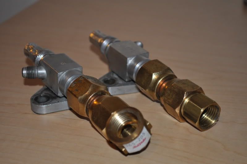
Compressor input and output connectors
These go from what was on my YORK input and output to NPT (national pipe thread). Some Yorks have flange mount threads and some have tube-O threads. Somehow you need to get those to fit your intake filter and your outgoing hose. Kilby sells special fittings for this at $45 x 2. I found an alternative "fitting" at the hardware store for $5 and screwed them onto the original fittings that were on the top of the York from when it was and air conditioner compressor
acp20019.jpg

acp20022.jpg

acp27.jpg


High pressure hydraulic hose
When the air is first coming out of the compressor it is under a lot of pressure, is very hot and has lots of water and oil in it. Other write ups suggest you run at least a few feet of good hose before you get to the filter. For this first section between the compressor and the coalescent filter I ran a 6’ long hydraulic hose. These hoses can handle very high pressure as they are double steel braided and the end has a 1/2” NTP thread. $15 at the farm supply store.
1819981.jpg


Coalescent filter
You can buy a basic plastic one at the hardware store but these York compressors throw out a lot of water from the air is is compressing and oil from the design. They are also running at high pressure and heat so a quality industrial strength filter style is a good thing here. I found one of the models Kilby sells but from a factory liquidator on ebay. Made from metal I snagged it for $20.
acp2002.jpg

acp2004.jpg


Check valve
This sits just past the coalescent filter in the system line. The check valve keeps all the high pressure air in the system. It is basically a one way valve and there are lots of styles of these out there. Just make sure the size allows for max air flow because at this point in the system there is still a lot of air moving from the compressor. I found one that had 3/8 NPT male on one end and 3/8” NPT female on the other.
060-800373.jpg


Air tank
There is a great pocket under the rear of an H2 for a 28” long tank that is about 7” – 9” in diameter. I ran across this aluminum Air Zenith 5 gallon tank on ebay that is designed for 200 psi and used for air suspension (lowriders) set ups. New it was a $85 tank and I picked it up for half that. I chose aluminum so I do not have to worry as much about moisture and rusting in the tank. Another alternative I looked at was to use air brake tanks from semis. These are strong enough and fall into that 28” size in length.
acp69.jpg


Pressure switch
This switch closes the circuit if there is not a set amount of air in the system. Once the “full” amount of air pressure is reached it opens the circuit, cutting power to the compressor clutch and causing the compressor to stop pumping in more air. You can buy these with different on and off pressure points. I chose on at 120psi and off at 150psi. There are also large ones designed for AC power cords that could be used but in the onboard design there are only 12 volts turning on a relay to power the clutch so I went with the basic low voltage style.
acp20010.jpg


I also collected all the miscellaneous items I was going to need.
Safety relief valves
Small manifold with 6+ npt female holes
Air hose
Small diameter high pressure hose to run to in cab gauges
NPT connectors of all types (spent more money on these then any single item)
Pressure gauges
Quick connects (found some in universal fit style)
Inline on/off valves (used for natural gas lines)
Lit toggle switche(s)
New seals for top of compressor fittings (.99 at auto parts store)
Wires, fuses
Relays
New H2 Gauge Pod that mounts on top of dash in driver corner
Steel plate for bracket
Mounting bolts
Mounting bracket
 
Last edited:

Chastan

Well-Known Member
Messages
149
Location
Reedsburg, WI
Post #3 Onboard Air

POST #3 CHAPTER THREE
The work begins….

Compressor oil limiting plug

There is a lot of discussion on the web about how much oil the York compressors kicks out with the compressed air. One modification that almost eliminates this issue is to plug an oil return “hole” inside of the compressor. This mod took me only a few minutes and I was careful to re-tork the bolts to York specs. You can find more about this topic and the York factory specs at the end of this thread under links.
acp20011.jpg
acp20012.jpg

acp19.jpg
acp20.jpg

acp23.jpg


Installing the Alternator Combination (Dual) Pulley
The power for the compressor is pulled from the alternator pulley spinning around. Swapping out the stock pulley with this one allows a second belt (v-belt) to go from the pulley to the compressor clutch wheel.
061-004.jpg

acp89.jpg

acp91.jpg

acp92.jpg
acp94.jpg

acp95.jpg

acp96.jpg

acp97.jpg

acp10.jpg
 
Last edited:

Chastan

Well-Known Member
Messages
149
Location
Reedsburg, WI
POST #4 Onboard Air

POST #4
The work continues

Custom Compressor Bracket Version 1.0

So I had to find a way to attach the compressor to the engine block and line it up with the alternator pulley. The alternator sits on an aluminum bracket so my first idea was to use a large piece of rectangular steel and bold one side to the alternator bracket and one to the compressor. By using this shape I though I could get in to bolt from the inside to both pieces.
acp83.jpg


I quickly realized that the steel was not wide enough for where I had to mount the compressor in relation to the belt. Plan B…
I could now see there was more then enough room on the side cavity of the compressor to accommodate a bolt head. So I now worked on a flat bracket to bolt to alternator bracket and then to the side of the compressor.
acp100.jpg

r-DSCF3581.jpg

acp99.jpg
acp98.jpg


I plasma cut the rectangular steel and kept an area of one side so that I had a 90 degree piece to bolt to the front of the alternator. This would give me stability in two major directions as the belt applied pressure.

This design worked but I had to still weld on a second plate to get the width I needed to reach all the compressor mounting holes. Here are some pictures of that first bracket.
acp15.jpg


Now I ran into a major mess up on my part. Somehow the holes in the bracket I built that the bolts to hold the compressor would go through did not line up with the alternator pulley groove. They were off by a few degrees but that meant the belt would run correct at the top but at one heck of an angle at the bottom.
acp17.jpg

acp31-1.gif


Done for that night I knew I would have to redo the bracket from scratch.


Custom Compressor Bracket Version 2.0
Update 10.27.2011. On one of the nights I was working on the brackets my phone got left out in the rain. I had thought I lost all the pictures but it turns out my IT guy had my photos being synched at work so I have gone back and added some not posted until now.

So back to the steel supply shop. For the second try I got a piece of 3/8 inch steel plate wide and tall enough for what I needed. This time around I mounted the bracket and confirmed the placement of the compressor before I drilled holes to mount it. I also waited on the 90 degree piece. I used the V 1.0 as a template for that piece but this time I mounted everything to the truck, trimmed the 90 degree piece until it was perfect and then spot welded it in place while it was in place on the truck. This eliminated any error that I would have the front hole position mess up the side hole positions.
acp42.jpg

acp33.jpg


Adjusting the radiator hose
To buy some extra space and insure the new compressor and belt did not rub against the radiator hose I cut off two inches and re-attached. This pulled the hose in but did not affect flow.
acp28.jpg


Relocating the engine computer.

When I mounted the compressor on the first bracket it fit but it was also touching the engine computer plastic housing. With the compressor attached to the engine and the housing attached to the frame (sort of mounted to the right and below the battery) I knew there would be too much rubbing going on. As I un-mounted the computer I realized I only had a little give in all the wires that go into it. On a temporary basis I flipped it up and zip tied it between the brake master cylinder and the intake manifold. Here is some info on that specific part of the project.

acp81.jpg

acp82.jpg

acp87.jpg

acp85.jpg


To find a permanent home for the computer I built a bracket that would also be home to a series of relays. Although I am only using one for this project I am ready to go for off road lights and a winch controlled through these relays.


acp43.jpg

IMG00006-20110819-2220.jpg

IMG00008-20110819-2221.jpg

IMG00009-20110819-2223.jpg

IMG00011-20110819-2225.jpg

IMG00022-20110820-2033-1.jpg


IMG00025-20110820-2043.jpg


acp44.jpg

acp61.jpg

 
Last edited:

Chastan

Well-Known Member
Messages
149
Location
Reedsburg, WI
Post #5 Onboard Air

POST #5
The work continues

Plumbing the air system.
With the compressor in, I am going to walk through the air system plumbing from compressor to the air tank and then to the quick connects.

acp64-1.jpg

acp49.jpg

acp57.jpg

acp55.jpg

acp53.jpg

acp54.jpg

acp30017.jpg


Air tank install
Most of these pictures of the air tank are from after I went off roading so it is pretty dirty up there. Basically I took a long L bracket that has lots of mounting holes in it and bolted it through the inside floor. Then I steel banded the tank to this bracket. In addition there was a natural bump in the ribs of the undercarriage so the tank it wedged between these bumps, the L bracket, and the bands. It came out very solid and I would do the exact same thing the next time.
IMG00035-20110820-2334.jpg


Here you can see the location of the tank in the back
acp3009.jpg

acp30010.jpg

acp3005.jpg


IMG00037-20110821-0027.jpg


Bolts from the back floor down to the bracket
acp3003.jpg

acp90-1.jpg


IMG00039-20110821-0222.jpg


acp30011.jpg


IMG00038-20110821-0221.jpg

IMG00034-20110820-2334.jpg

IMG00039-20110821-0222.jpg

acp30016.jpg

 
Last edited:

Chastan

Well-Known Member
Messages
149
Location
Reedsburg, WI
Post #6 Onboard Air

POST #6
Still more work to be done.

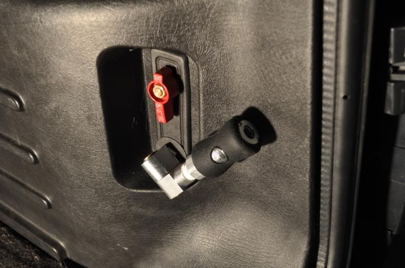
Quick connects
The rear compartment installation will be permanent. The front install is in place until I build custom bumper ends that will have quick connect and coil hoses stored in them. More on that later.

Rear quick connect install

acp35.jpg

acp37.jpg

acp38.jpg


Front quick connect install

acp30036.jpg
acp50.jpg

acp51.jpg

acp30033.jpg

acp30031.jpg


Wiring Plan

Here is the wiring diagram. A
big thanks goes out to F5 for his help in locating a good wire to tie the switches into up in the roof console. In fact I call this the “F5 Design”

H2WireDiagramPage1of2.jpg

H2WireDiagramPage2of2.jpg


Electrical set up, hose and wire runs

acp39.jpg

acp40.jpg

acp41.jpg

acp30025.jpg

acp8.jpg

acp30034.jpg

acp71.jpg
acp30023.jpg

acp59.jpg

 
Last edited:

Chastan

Well-Known Member
Messages
149
Location
Reedsburg, WI
Post#7 Onboard Air

Post # 7 CHAPTER FOUR
Its working!!!! …and now what is left to do.

V-belt
So after getting everything installed I headed off to the auto parts store to get a V-belt to use on the set up. I thought this would be one of the easier things to find. Turns out the size I needed fell in between two common sizes. The only belt I could get in the correct diameter was a belt designed for lawn mowers. This belt works but after using it at idle speed – 2000 rpm I left it on for normal driving. It could not hold up to the extended RPM.s and is already breaking down.

I have to say that there was some personal satisfaction using my own onboard air system after off roading on Drummond Island. I could have stopped at the gas station on the way off the island but this air just seemed a little “sweeter”

UPDATE 4/5/2012. After much search I found the perfect belt for my set up. Works great now at all speeds and no belt issues.


Toggle Switches and gauges mounted
I still need to mount the 6 other toggle switches and find some gauges to go in the gauge pods. Good thing is that the difficult wire and hose runs are done.
acp30034.jpg


Front bumper end boxes
I am excited about this one. I am replacing the cheap plastic triangle bumper ends with steel diamond plate (I will paint black) boxes that run a little deeper but will look the same from the front. These boxes will have a sealed door on the side and will serve several purposes. Inside I will have a quick connect, coil hose that will reach to the back tires. I will also add a little “pocket” to hold miscellaneous tire items like pressure gauges and deflators. I will also use the front face of the box to add another set of off road flood lights. Here are some shots of the design and raw material.
acp30035.jpg

acp30037.jpg

acp74.jpg

acp76.jpg


Train horn
Now that I have an air tank with 150 psi in it I can install a great train horn. Have not started planning that one yet


Rerun air hoses for better quality
I also plan to rerun some of my air hoses. The orange stuff I used is showing the pressure. I think it is rated for a lower pressure then I remember.
 
Last edited:

Chastan

Well-Known Member
Messages
149
Location
Reedsburg, WI
Post #8 Onboard Air

POST #8 CHAPTER FIVE (last post in series)
Resources and links

General info
Kilby web site

http://www.kilbyenterprises.com/compressors.htm

Kilby FAQ and set up diagram
http://www.kilbyenterprises.com/faq.htm

Write ups of other builds info
http://www.jedi.com/obiwan/jeep/yorkair.html
http://www.stu-offroad.com/otherwriteups/oba/oba-1.htm
http://www.offroaders.com/info/tech-corner/project-cj7/project-cj7-onboard-air.htm
http://coloradok5.com/york.shtml
http://www.kilbyenterprises.com/web-instructions/oba_manual.pdf


Topic specific links
Oil in the system and oil mod.
Read second half for easy way
http://www.rockcrawler.com/techreports/york_mod/index.asp
http://www.jedi.com/obiwan/jeep/york_lube.html

List of vehicles that had York 210's in them if you go searching in a junk yard
http://www.links4jeeps.com/writeups/york/York_Donors.php
http://www.fullsizebronco.com/forum/archive/index.php/t-82159.html

Identification of the compressor model types
http://www.offroaders.com/info/tech-corner/project-cj7/project-cj7-onboard-air-York-ID.htm

York Compressor Specifications
http://www.kilbyenterprises.com/york.htm

Where to buy some of the items
This Ebay store sells a lot of compressors including rebuilt Yorks in the clutch and output side you want.
http://stores.ebay.com/bestaccompressor?_trksid=p4340.l2563

Site for a tank that will fit back of an H2 perfect.
http://shop.air-zenith.com/blackaluminumairtank.aspx

intake filter
http://www.solbergmfg.com/ViewSeriesDetail.aspx?SeriesId=1&PartNumber=FS-06-050

Item COST CHART
Posting up soon….

 
Last edited:

Ron B

Well-Known Member
Messages
359
Location
Los Angeles
really nice job! I would love to get a belt driven compressor but need 200+ psi and the only ones I can find are 150 max!!
 

Chastan

Well-Known Member
Messages
149
Location
Reedsburg, WI
really nice job! I would love to get a belt driven compressor but need 200+ psi and the only ones I can find are 150 max!!

You just need to carve out enough space in your engine bay to fit one of these...
http://gkisupply.com/product.php?id_product=13

13-53-large.jpg


With the right pulleys you shuld be able to use a much smaller fly wheel then seen here. This is a diameter needed from a 5HP electic motor.
 

MaxPF

AGNTSA
Messages
1,394
Location
The dark side of the globe

Ron B

Well-Known Member
Messages
359
Location
Los Angeles
thanks -- I have seen both the ones linked. Unfortunately the GKI is no longer available and the Oasis is Uber-huge/heavy and takes 180 amps! I guess I will stick with my Viair 480C, it's half the size and 22 amps vs 180 on the Oasis. Bummer. Always looking for a better pump but maybe I should just stick with what works (and fits!).
 
Top